Email: anwenqq2690502116@gmail.com
Disinn ta 'substation intelliġenti tat-tip kaxxa 10kV ibbażat fuq pjattaforma Gizwits IoT + STM32
Is-sistema intelliġenti ta 'kontroll mill-bogħod tas-substation tat-tip kaxxa 10kV introdotta f'dan l-artikolu ġiet iddisinjata u żviluppata minn Tian Hui ta' Xi'an Università tax-Xjenza u t-Teknoloġija.
Is-sistema tieħu d-disinn ta 'sistema intelliġenti ta' 10kV li tbiddel il-kaxxa għal appartament student f'kulleġġ bħala l-isfond tal-inġinerija, u jiddisinja sistema intelliġenti ta '10kV li tbiddel il-kaxxa bbażata fuq il- Internet tal-Oġġetti. Is-sistema tikkonsisti fi tliet partijiet: saff ta' perċezzjoni, saff ta' komunikazzjoni u saff ta' applikazzjoni. Is-saff tal-perċezzjoni huwa responsabbli għall-ġbir u t-trażmissjoni tad-dejta tas-sensuri lill-kontrollur tal-kamp.
Inkluż tagħmir sekondarju tas-sistema bħal apparat għall-protezzjoni tal-mikrokompjuters, miters tan-netwerk intelliġenti, u kontrolluri intelliġenti ta' kumpens għall-potenza reattiva, kif ukoll tagħmir għall-individwazzjoni ambjentali bħat-temperatura u l-umdità, Duħħan, u sensuri tal-immersjoni tal-ilma. Il-kontrollur fuq il-post juża mikroproċessur inkorporat STM32, inkluż wiri LCD, modulu tal-allarm bil-vuċi, modulu ta 'komunikazzjoni relay u GPRS, eċċ.; is-saff ta 'komunikazzjoni juża komunikazzjoni mingħajr fili GPRS, li huwa responsabbli għat-trażmissjoni bidirezzjonali tad-data bejn il-kontrollur fuq il-post u l-pjattaforma tal-cloud; Il-pjattaforma tal-cloud Gizwits tiżviluppa sistema ta 'monitoraġġ mill-bogħod u app mobbli għal transformers tat-tip kaxxa, li huwa responsabbli għall-ħżin, Analiżi u pproċessar tad-dejta tal-operazzjoni tat-transformer tat-tip tal-kaxxa.
This system finally realizes the user's remote monitoring of environmental parameters such as variable temperature and humidity, allarm tad-duħħan u ilma tal-fossa tal-pedamenti, kif ukoll parametri elettriċi bħall-kurrent, Vultaġġ, frekwenza u fattur ta' potenza, u l-istatus ta' ħidma tat-tagħmir permezz tal-WEB tal-kompjuter jew l-APP mobbli.
Meta jkun hemm anormalità jew ħsara fit-tħaddim tat-transformer tat-tip kaxxa, is-sistema ta' monitoraġġ tiġġudika awtomatikament il-livell ta' ħsara, u jibgħat allarm permezz ta' kombinazzjonijiet differenti ta' qanpiena fuq il-post, APP TAT-TELEFOWN ĊELLULARI, SMS u telefon, eċċ., u jinnotifika lill-persunal rilevanti biex jelimina problemi moħbija fil-ħin u jipprevjeni inċidenti elettriċi. . Huwa adattat għal monitoraġġ mill-bogħod u ġestjoni ċentralizzata ta 'transformers tal-kaxxa u kmamar tad-distribuzzjoni tal-enerġija, u tista' ttejjeb ħafna l-livell ta' intelliġenza u s-sikurezza tal-provvista tal-enerġija u l-affidabbiltà tat-tagħmir tad-distribuzzjoni tal-enerġija fl-iskejjel, intrapriżi u komunitajiet.
1. Introduzzjoni
Bil-kostruzzjoni u l-iżvilupp tal-ekonomija soċjali u n-netwerk tad-distribuzzjoni, hemm aktar u aktar transformers tal-kaxxa 10kV. Is-substation tradizzjonali tat-tip kaxxa 10kV ġeneralment tadotta l-mod ta 'operazzjoni ta' spezzjoni regolari mhux weħidha u manwali, li għandu livell baxx ta' intelliġenza u m'għandux sistemi remoti ta' monitoraġġ u allarm ta' ħsarat għall-ambjent u t-tagħmir. Bhalissa, bl-iżvilupp rapidu tat-teknoloġija tas-sensuri intelliġenti, teknoloġija inkorporata, teknoloġija tal-komunikazzjoni u teknoloġija tal-cloud computing u t-tnaqqis tal-ispiża, is-substation tat-tip kaxxa intelliġenti 10kV ibbażata fuq l-Internet tal-Oġġetti saret l-aħjar għażla għat-titjib u t-trasformazzjoni ta 'substations tradizzjonali tat-tip kaxxa.
Is-sistema intelliġenti ta 'monitoraġġ remot tas-substation tat-tip kaxxa bbażata fuq l-Internet tal-Oġġetti tista' tissorvelja mill-bogħod l-ambjent tas-substation tat-tip kaxxa, parametri operattivi u l-istatus tat-tagħmir f'ħin reali. Kif muri fil-Figura 1.
L-utenti jistgħu jimmonitorjaw mill-bogħod parametri ambjentali bħat-temperatura u l-umdità tal-kaxxa, allarm tad-duħħan, u akkumulazzjoni tal-ilma fil-fosos tal-pedamenti, kif ukoll parametri elettriċi bħall-kurrent, Vultaġġ, Frekwenza, u l-fattur tal-enerġija, u l-istatus tat-tagħmir permezz ta' kompjuters jew APPs mobbli fi kwalunkwe ħin. Meta s-substation tal-kaxxa taħdem b'mod anormali jew tfalli, is-sistema ta' monitoraġġ tinnotifika awtomatikament lill-persunal rilevanti permezz ta' metodi differenti ta' APP tat-telefon ċellulari, SMS u telefon skont il-livell ta' ħsara, sabiex jiġu eliminati ħsarat moħbija fil-ħin u jiġu evitati inċidenti elettriċi.

10substation tat-tip kaxxa intelliġenti kV ibbażata fuq l-Internet tal-Oġġetti
Is-sistema ta' monitoraġġ mill-bogħod tas-substation tat-tip ta' kaxxa intelliġenti tikkonsisti f' "fieldbus LAN" ġewwa s-substation tat-tip kaxxa u "Netwerk ta' żona wiesgħa tal-pjattaforma tal-cloud" barra s-substation tat-tip kaxxa. Dan il-mudell strutturali jista' jiġi applikat għall-iżvilupp ta' sistemi ta' monitoraġġ mill-bogħod għal sistemi sekondarji ta' monitoraġġ mill-bogħod ta' tagħmir tal-provvista tal-ilma, Sistemi ta' ġestjoni taċ-ċarġ tal-elettriku residenzjali, u sistemi ta' monitoraġġ mill-bogħod tal-liftijiet biex jittejjeb il-livell ta' intelligence u ġestjoni tat-tagħmir tradizzjonali u jiġi promoss it-titjib tal-industriji tradizzjonali. Għandu valur tajjeb ta 'applikazzjoni.
2. Disinn ġenerali tal-programm
Id-disinn ta 'substation tat-tip kaxxa intelliġenti bbażata fuq l-Internet tal-Oġġetti huwa bbażat fuq id-disinn ta' substation tat-tip kaxxa intelliġenti ta '10kV f'appartament ta' student tal-kulleġġ. Id-disinn tas-sistema primarja tat-transformer intelliġenti tat-tip kaxxa 10kV huwa l-istess bħal dak tat-transformer tradizzjonali tat-tip kaxxa 10kV, u għandha t-tendenza li tkun matura. Dan l-artikolu jiffoka fuq id-disinn intelliġenti tat-transformer tat-tip kaxxa intelliġenti 10kV. Dan li ġej huwa ħarsa ġenerali qasira tal-kontenut tad-disinn tas-sistema primarja tat-transformer tat-tip tal-kaxxa intelliġenti 10kV.
2.1 Disinn tas-sistema primarja ta 'substation intelliġenti tat-tip kaxxa 10kV
It-tagħbija tal-enerġija tan-Nru. 5 bini ta 'appartament student f'università huwa prinċipalment dawl, kompjuters u tagħbijiet tal-kundizzjonaturi tal-arja miżjuda ġodda. Kull dormitorju huwa kkalkulat bħala 8 nies, it-tagħbija tad-dawl hija 100W, each student computer load is 200W, and each 1.5P split-type hanger is newly installed with air conditioners The power is 1.3kW, and the load of a single dormitory is 3.0kW. Skond il- "Industrial and Civil Power Supply and Distribution Design Manual", the dormitory's power load demand coefficient is 0.7, and the power factor is 0.8.
Considering the increase of the electricity load of the student apartment in the future, the transformer needs to reserve a certain margin, and the transformer with a capacity of 1000kVA is selected. Considering the initial investment cost and operating cost of the transformer, as well as the requirements of the national energy conservation and emission reduction policy, the low-loss fully sealed oil-immersed transformer S13-M-1000/10-0.4 is selected for this purpose.
On the basis of load statistical calculation, short-circuit calculation, dynamic stability verification and thermal stability verification, the main equipment of the primary system of the box-type transformer is selected. The specific models and technical parameters of the main equipment of the primary system are shown in Table 3, Table 4, Table 5 and Table 6.
According to the design requirements of the No. 5 student apartment project box substation and the primary system design calculation, the main wiring diagram of the designed primary system of the No. 5 student apartment box substation is shown in Figure 2.

Figura 2 : The main wiring diagram of the primary system of a box-type substation in a student apartment in a university
2.2 Intelligent Design Scheme of 10kV Box Transformer
Aiming at the design defects and problems existing in the operation management of the 10kV traditional box-type substation, the key to solving the problem lies in the construction of a closed-loop system for the detection, remote monitoring and alarm of the intelligent box-type substation environment and equipment, and the design has remote monitoring of the operating environment and electrical equipment The intelligent box transformer system with various functions can collect and monitor environmental parameters such as box transformer access control, temperatura ambjentali u umdità, allarm tad-duħħan, and water in the cable trench, as well as voltage, current, active power, reactive power, power factor, cable temperature, transformer transformer, eċċ.
Body temperature and gas alarm signal and other equipment operating parameters, remote control exhaust fan, microcomputer protection device and circuit breaker switch.
The system adopts smart instruments and smart sensors with communication functions commonly used in industrial sites, and transmits the collected data to the field controller through field bus communication, and the field controller transmits the data to the server or cloud host computer through a wireless or wired communication module. Realize functions such as telemetry, remote signaling and remote control.
The remote monitoring system of 10kV intelligent box transformer based on the Internet of Things uses intelligent instruments and sensors with digital two-way communication function, and uniformly adopts standard RS485 bus interface and Modbus-RTU communication protocol. The remote monitoring system of intelligent box transformer based on the Internet of Things is composed of three parts: the perception layer, the communication layer and the application layer.
* Saff ta 'perċezzjoni: through various smart meters and smart sensors to collect various environments, equipment operating parameters and equipment working status of the box transformer, and transmit the data to the field controller through the RS485 bus. The field controller has a built-in operating system and has data collection, Computing, processing and control functions.
* Communication layer: This layer is the connection and link of data transmission and exchange, and is responsible for the two-way transmission of data between the cloud platform and the on-site controller. According to the actual communication conditions of the box-type transformer, various communication methods such as wired optical cable, Ethernet or wireless GPRS can be selected to transmit data to the cloud platform.
*Applikazzjoni saff: Design and develop a remote monitoring system for box-type transformers on the cloud platform, responsible for the sending, receiving and processing of historical data, remote monitoring of box-type transformer operating parameters, and record storage and analysis of event operation data. And develop WEB and mobile APP on the cloud platform, the electrician on duty can monitor the operation data and equipment working status of the box transformer at any time through the computer or mobile APP.
3. System hardware design
3.1 RS485 bus local area network of the box transformer site
With the development and progress of embedded technology and the reduction of cost, many detection instruments, sensors and actuators have built-in microprocessors for the shortcomings and problems of information transmission of traditional box-type field equipment, which can complete AD\DA conversion and linearization and digital filtering. A serial communication data interface is added inside these digital field devices, and the serial two-way communication between field devices can be realized by using a unified standard communication protocol.
Mainly used industrial bus network at present.
One of the keys to the design of the remote monitoring system for smart box-type transformers is to select smart instruments and sensors with digital two-way communication functions, and to adopt standard and unified bus interfaces and communication protocols. Starting from the engineering practice of the 10kV smart box-type transformation design in the No. 5 student apartment, the RS485 bus and Modbus-RTU communication protocol generally supported by smart sensors are selected.
According to the main wiring diagram of the primary system of a box-transformer in a student apartment in a college and the system block diagram of the 10kV intelligent box-transformer remote monitoring system, the system hardware design takes the box-transformer field controller as the core, and consists of a microcomputer integrated protection device, an intelligent network meter and an intelligent reactive power Secondary system equipment such as compensators, and environmental detection sensors such as temperature and humidity smoke sensors, PT100 temperature sensors and water intrusion sensors form the RS485 bus local area network of the box-to-box transformation site. The RS485 bus local area network system diagram of the box transformer is shown in Figure 4.
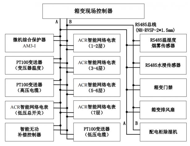
RS485 bus local area network system diagram of the box-type transformation site
(1) RS485 serial communication bus
The communication mode of RS485 bus is master-slave mode, and the master device polls each slave device for communication, and one-to-multi-point networking can be established to form a distributed system. The RS485 interface is a widely used low-speed serial interface, and the RS485 interface has the following characteristics.
* RS485 interface.
RS485 interface communication adopts differential transmission mode, and has a combination of balanced driver and differential receiver, and uses the voltage difference at both ends of the cable to transmit signals, which greatly enhances the ability to resist common-mode interference and anti-noise interference.
* RS485 bus has high transmission rate and long transmission distance. The maximum transmission distance is about 1200 metri, and the maximum transmission rate is 10Mbps; its transmission rate is inversely proportional to the transmission distance, and the maximum transmission distance can be reached when the rate is below 20kbps.
* Support multiple nodes. Ġeneralment, an RS485 bus loop can theoretically support 247 device nodes.
(2) Modbus-RTU serial communication protocol
The Modbus protocol is applied to the industrial bus network. Through the protocol, data communication can be carried out between the controller and the field equipment. The equipment produced by different manufacturers can form an industrial bus network monitoring system following a unified protocol. The protocol has a master-slave structure, one master node in the network, and the others are slave nodes, and each slave node has a unique device address.
In the serial bus network, the master node starts a command, and all slave devices will receive the command. The Modbus command contains the address of the slave device that executes the command, and the slave device designated by the master device responds first and then executes the command. There are checksums in the Modbus commands to make sure that the arriving commands have not been corrupted. Modbus commands can instruct the RTU to change its register value, read or control the I/O port, and order the device to return one or more register data.
Modbus includes ASCII, RTU and TCP three message types. ASCII transmission mode, LRC checksum, low transmission efficiency, but intuitive, simple and easy to debug. RTU transmission mode, using CRC check, effiċjenza għolja tat-trasmissjoni, slightly more complicated than ASCII. Ġeneralment, if the amount of data to be transmitted is small, you can consider using the ASCII protocol; if the amount of data to be transmitted is relatively large, it is best to use the RTU protocol. Għal din ir-raġuni, the intelligent instruments and sensors of this system adopt the Modbus-RTU communication mode uniformly.
3.2 Hardware Design of Field Controller of Box Transformer
The field controller of the box transformer is composed of an embedded system. The embedded system is application-centric, software and hardware can be tailored, and realizes equipment automation, intelliġenza, and remote monitoring functions. It is mainly composed of embedded microprocessors, related hardware, sistemi operattivi inkorporati, and application software systems.
(1) STM32 microprocessor minimum system
The minimum system of embedded microprocessor includes embedded microprocessor, reset circuit and debugging circuit. The clock circuit provides the required external clock signal, the reset circuit provides a unified initial state, and the debugging circuit provides an interface for program download and debugging.
* Embedded microprocessor option. According to the requirements of the 10kV intelligent box transformer remote monitoring system for the performance of the on-site controller, this system chooses the STM32F103ZET6 chip as the core microprocessor of the on-site controller. STM32F103ZET6 embedded microprocessor, MCU has high integration, konsum baxx ta 'enerġija, and high cost performance. It is suitable for various application requirements in the industrial medical field, and can meet the requirements of data acquisition and real-time processing of this system.
* Crystal oscillator circuit. The crystal oscillator circuit provides a fixed frequency pulse to the microprocessor to make the microprocessor operate normally. The STM32 microprocessor has two crystal oscillators, the 8MHz crystal oscillator provides an external high-speed clock, and the 32.768KHz crystal oscillator provides an external low-speed clock.
* Reset circuit. The function of the microprocessor reset circuit is to restart the system. When the system fails, press the reset button to restart the device. Ġeneralment, the reset circuit uses a low-level signal to restart.
(2) Power circuit design
The system selects a DC external power supply with a rated voltage of 12V (2A), and selects a DC 5V (2A) power adapter with a USB interface to supply power to the field controller. The 12V DC power supply is connected to the control board, and the DC 12V power supply is stepped down to obtain a DC 5V power supply through the LM2596S step-down module. The 5V voltage is then passed through the AMS1117-3.3V regulator chip to obtain a 3.3V voltage to supply power to the STM32 chip. The circuit diagram of LM2596S and AMS1117-3.3V power supply regulator is shown in Figure 8.
(3) RS485 interface to TTL module
The RS485 interface to TTL module realizes the two-way conversion and communication of RS485 signal and TTL signal, but the signal must be executed alternately, and cannot be carried out in two directions at the same time. All field devices use this module to connect with the microcontroller, and the wiring diagram is shown in Figure 9.

Wiring Diagram of TFT-LCD and STM32 MCU - Figura 9
(4) LCD display module
Since the on-site controller of the box-type remote monitoring system needs to display many numbers and characters, a 2.8-inch TFT-LCD liquid crystal display is selected as the display module, and there is an ILI9341 controller inside. Consider STM32 can communicate with ILI9341 through SPI interface, 8080 interface or RGB interface. In order to achieve a faster refresh rate, TFT-LCD uses 8080 parallel data bus interface. STM32 outputs data to the ILI9341 controller memory through the variable static memory FSMC module.
(5) Voice alarm module
When the STM32 microprocessor detects that there is an abnormality or fault in the operation data of the box transformer, it will send a message to the serial port and start a voice alarm. The voice alarm module selects the commonly used voice chip SYN6288, and automatically broadcasts voice alarm information according to the programmed program. The system uses GB2312 code, which is suitable for information exchange in Chinese character processing and Chinese character communication. The SYN6288 also accurately recognizes numbers, times and dates, and commonly used units of measurement.
(6) Relay module
The field controller selects a group of 2-way optocoupler isolation relay modules to control the opening and closing of the DC 12V alarm bell and fan, and the 220V AC solid state relay can be selected according to the power supply type and power of the box-type exhaust fan. Each relay circuit module has normally open and normally closed contacts, as well as LED status indication; each relay circuit is isolated by optocouplers, and is equipped with a freewheeling diode to release the induced voltage of the relay and protect the previous circuit. When the ambient temperature of the box transformer exceeds a certain range, the on-site controller outputs a high level, and one optocoupler isolation relay acts to turn on the fan to cool down; when serious faults such as excessive smoke concentration occur, the controller drives another optocoupler isolation relay to connect The alarm bell loop sends out an on-site alarm. For the working principle diagram of the relay and the connection diagram between the relay module and the STM32 chip, please contact the manufacturer and send the request.
(7) Communication module
According to the design requirements of the 10kV intelligent box transformer remote monitoring system, the communication between the intelligent box transformer and the cloud chooses the GPRS wireless communication method with low traffic cost. Gizwits firmware GPRS module.
*Gizwits firmware GPRS module (G510_GAgent firmware). This module is an application program running on various communication modules, providing functions such as two-way transmission of cloud and product device data, device configuration into the network, discovery and binding, and program upgrades. The circuit diagram between the GPRS module and the main controller can be obtained by contacting the manufacturer.
*GPRS-GA6 module. This module can realize the transmission of voice, short message and data with low power consumption. It is suitable for various design requirements in M2M applications, especially for the design of compact products. It-tieni, the communication protocol adopts UART serial port bus transmission, uses standard AT commands to control the module, and selects the baud rate of 115200bps. Contact the IoT manufacturer for the connection circuit diagram of the GPRS-GA6 module and the STM32 microcontroller.
3.3 Microcomputer comprehensive protection device
According to the power transformer protection design specification (GB/T 50062-2008), 10kV transformers usually need to install overcurrent protection with time limit. The microcomputer protection device has the protection, measurement and control functions of transformers and lines, as well as the functions of data acquisition, monitoring and system self-inspection, and has high sensitivity and reliability.
According to the design requirements of the 10kV intelligent box change in the student apartment, the Ankerui AM3-I current-type microcomputer comprehensive protection device with RS485 communication function is selected, with IA, IB, IC, UA, UB, UC, P, Q, Fr and other electric Parameter measurement, 8-channel external switch signal acquisition, and circuit breaker remote control opening and closing operations and other functions. The wiring terminal diagram of AM3-I microcomputer protection device is as follows:

Wiring terminal diagram of AM3-I microcomputer protection device
3.4. Smart network meter
Smart network meters are used to detect electrical parameters such as three-phase current, voltage and power of low-voltage power distribution circuits, as well as the opening and closing status of isolating switches and circuit breakers. According to the design requirements of the secondary system of 10kV intelligent box transformer, Ankerui ACR intelligent network meter with RS485 communication function is selected, and the wiring diagram of ACR intelligent network meter and low-voltage current transformer and the wiring diagram of switch input and output are selected.
ACR smart network meter low-voltage current transformer and digital input and output wiring diagram
ACR smart network meter adopts Modbus-RTU protocol, which can measure and collect power parameters. The switch input function can detect the switching status of the isolating switch and circuit breaker, and the relay output function can remotely turn on and off the circuit breaker. The ACR intelligent network meter has a unified plan for the communication address table, which can realize the three remote functions of telemetry, remote signaling and remote control.
(1) AD conversion and calculation of AC analog signal
Il- 3 phase voltage signals and 3 current signals (current transformer output signals) directly collected by the ACR smart network meter are all analog quantities, which need to be converted into digital signals that can be recognized by the CPU for data processing. L-ewwel, il 3 phase voltages of 220V and 3 current analogs are transformed into low-voltage signals through the converter, and converted into the voltage allowed by the AD converter through a voltage forming loop; , converted into a digital signal by AD and input to the CPU. The schematic diagram of the sampling and AD conversion process of the AC analog quantity can be obtained by contacting the manufacturer.
* Analog voltage conversion and low-pass filtering. The function of the voltage forming circuit is to electrically isolate and transform the electricity. Ġeneralment, the AD converter requires the input signal to be ±5V and ±10V, so the transformation ratio of the voltage converter can be determined. Low-pass filters are divided into passive filters and active filters. Active filters are composed of capacitors, resistors and integrated operational amplifiers, which amplify the signal while filtering. Passive filters only have filtering functions but no signal amplification functions.
* Analog signal sampling. The sampling process should follow Shannon's sampling theorem, jiġifieri, the sampling frequency must not be less than 2 times the highest frequency of the input signal. The sampling process is very fast. The current AD converter sampling has reached the nanosecond level, while the sampling period of the power system automatic device is at the millisecond level, so the voltage and current signals of the six loops can share one AD converter, but the sampling circuit Must be equipped with a sample-and-hold device and a multiplexer switch.
* AD conversion. AD converters include successive approximation, integral, counting, parallel comparison, and VFC voltage-frequency converters. The successive approximation AD converter is a representative of both speed and precision in the ADC, and it has a higher conversion resolution at a higher conversion rate.
(2) Half cycle absolute value integration algorithm of sinusoidal electric quantity
The key of the software algorithm is to improve the accuracy and speed of the algorithm operation. The key of the AC sampling algorithm of the smart meter is to solve how to calculate the amplitude or effective value of the sinusoidal sampling signal according to the instantaneous value of the sinusoidal signal. The most commonly used algorithm for sine quantities is the half-cycle absolute value integration algorithm. The principle of the half-cycle absolute value integration algorithm is that the integral of the absolute value of the sine quantity in any half cycle is a constant S, and the integral value constant S has nothing to do with the integral start angle . The half-cycle absolute value integration algorithm based on the sine function model is shown in Figure 19.

Algoritmu ta 'integrazzjoni ta' valur assolut ta 'nofs ċiklu bbażata fuq mudell ta' funzjoni sine
The expression for calculating the effective value of the current by using the half-cycle absolute value integral algorithm is shown in the figure below:

In the formula, S represents the integral of the absolute value within half a cycle; I represents the effective value of the current; i represents the instantaneous value of the current; w represents the angular velocity; T represents the AC power cycle; f represents the AC power frequency; N represents the number of samples in one cycle ; Ts represents the sampling period.
3.5 RS485 temperature and humidity smoke sensor
Considering that the power supply line in the box-type transformer may have leakage, overload, short-circuit and excessive contact resistance, which may cause fires, and the failure of the fuel oil-immersed transformer may cause fires. Għalhekk, it is necessary to install a smoke sensor in the box-type transformer for fire detection of the box-type transformer. In order to detect potential failures early. In order to ensure the measurement accuracy and reduce the cost at the same time, the RS485 temperature, humidity and smoke three-in-one sensor is used to detect the temperature, humidity and smoke concentration in the box transformer. Il- temperature and humidity sensor uses the SHT30 probe. On-site surge and pulse interference. The sensor has 4 wires: red, black, yellow, and green. For the specific wiring method of the temperature and humidity smoke sensor, please contact the IoT manufacturer.
The smart meters and sensors designed in this system adopt the Modbus-RTU protocol, which can communicate reliably within the full baud rate range of 1200-115200. The baud rate of smart meters and sensors is uniformly set to 9600bps. The data transmission format and data conversion format of the sensor are as follows:
Sensor data query frame format. The sensor follows the standard Modbus-RTU protocol, and the sensor reading is stored in the holding register, and the function code is 04. The upper computer reads the sensor data inquiry frame format, and the lower computer sensor data inquiry frame format.
3.6 PT100 temperature transmitter - working principle of RTD PT100 - working principle of temperature sensor
PT100 temperature transmitter is used to detect transformer body temperature, high voltage and low voltage cable temperature, it is suitable for various industrial sites. Transformer will produce losses during operation, mainly iron loss and copper loss, also known as core loss and load loss. Copper loss varies with the load current and is proportional to the square of the load current. Transformer loss calculation formula is as follows:
In the formula, P0 represents the active power of the transformer in no-load operation at the rated voltage; I1 and I2 represent the high-voltage line current and the low-voltage side line current; R1 and R2 represent the high-voltage side resistance and the low-voltage side resistance.
The PT100 temperature transmitter is embedded with RS485 bus interface, and each temperature transmitter can be connected to 4 PT100 temperature sensors.
3.7 Working principle of water immersion transmitter
Due to the low water level of the box substation foundation pit, there is often water accumulation in the cable trench and foundation pit after the heavy rain, and there is a potential safety hazard of cable leakage, so irregular inspection and drainage are required. In this design, the water immersion sensor is used to detect the water accumulation in the foundation pit of the box substructure. The water immersion sensor applies the principle of liquid conduction, and uses electrodes to detect whether there is water. Select a contact type water immersion detector with RS485 communication function. The working principle of the water immersion detector is shown in Figure 23.
4. System software design
The system software design includes two parts: the field bus LAN software design of the box-type transformer and the remote monitoring system design of the box-type transformer based on the Gizwits cloud platform. The microcomputer integrated protection device, smart network meter and smart sensor in the field bus local area network of the box transformer have embedded application software, so only the software program design of the field controller of the box transformer is required.
4.1 Design of field controller software for box-type transformer
The field controller of the box transformer is an embedded system, and its software system is composed of application program, API, embedded operating system and BSP (board support package). According to the characteristics of many parameters, many tasks and high real-time requirements collected by the field controller of the 10kV intelligent box-type transformer, the μC/OS-Ⅲ embedded real-time operating system, which is widely used in commercial product development and teaching research, is selected. μC/OS-Ⅲ regards tasks as the smallest unit, and any task does not need to care about the specific management method of resources, which is determined by the operating system.
4.2 Software program design of field controller of box-type transformer
The entire software system design is based on the distributed system composed of intelligent instruments, sensuri, field controllers and cloud platforms, and the design and development of application software is carried out. Data transmission and exchange, the on-site controller and the Gizwits cloud server use the Gizwits communication protocol in the GPRS firmware for data transmission and exchange. The main program flow chart of the field controller application software of the box-type transformer.
*Software main program. L-ewwel, initialize all parts of the system, such as GPIO, serial port, clock, memory management, eċċ., and create tasks in μC/OS-Ⅲ. STM32 performs sensor data acquisition and processing, and sends correct information to LCD display. Fl-istess waqt, the STM32 sends AT commands to the GPRS-G510 module, exchanges data, connects to the Gizwits cloud platform through the LwM2M protocol, and judges whether the GPRS communication module is successfully connected to the Gizwits cloud server. If the connection is successful, data transmission is performed. Then judge whether the processed data is greater than the set threshold.
If it is a minor failure of the box substation, send the data information to the mobile APP through the cloud platform; if it is a general failure, send the data alarm information to the mobile APP through the cloud platform, and start the GPRS-GA6 communication module to send the alarm information through the mobile phone SMS; if If it is a serious fault, the data alarm information will be sent to the mobile phone APP through the cloud platform, and the GPRS-GA6 communication module will be activated to send the alarm information through the mobile phone text message and call the preset relevant personnel.


هل يمكنك تقديم شركة RFID IoT؟