Tölvupóstur: anwenqq2690502116@gmail.com
Hönnun á 10kV greindri aðveitustöð byggt á Gizwits IoT vettvang + STM32
10kV snjallt aðveitukerfi fjarstýringarkerfisins sem kynnt er í þessari grein var hannað og þróað af Tian Hui frá Xi'an vísinda- og tækniháskólanum..
The system takes the design of a 10kV intelligent box-changing system for a student apartment in a college as the engineering background, and designs a 10kV intelligent box-changing system based on the Internet hlutanna. The system consists of three parts: skynjunarlag, communication layer and application layer. Skynjunarlagið er ábyrgt fyrir söfnun skynjaragagna og sendingu til sviðsstjórans.
Þar með talinn aukakerfisbúnaður, s.s. örtölvuvarnarbúnaður, Greindur netmælar, og greindur viðbrögð máttur bætur stýringar, sem og umhverfisskynjunarbúnað eins og hitastig og rakastig, reykur, og vatnsdýfingarskynjarar. Stjórnandinn á staðnum notar STM32 innbyggðan örgjörva, þ.mt LCD skjá, rödd viðvörun mát, gengi og GPRS samskiptaeining, o.s.frv.; samskiptalagið notar GPRS þráðlaus samskipti, sem ber ábyrgð á tvíhliða gagnaflutningi milli stjórnandans á staðnum og skýjapallsins; The Gizwits ský pallur þróar ytri eftirlitskerfi og hreyfanlegur app fyrir kassa-gerð spenni, sem ber ábyrgð á geymslunni, Greining og úrvinnsla gagna um kassagerð spenni.
This system finally realizes the user's remote monitoring of environmental parameters such as variable temperature and humidity, reykskynjari og grunngryfjuvatn, sem og rafmagns breytur eins og straumur, spenna, Tíðni og aflstuðull, og búnað vinna stöðu í gegnum tölvuna WEB eða farsíma APP.
Þegar það er frávik eða galli í rekstri kassa-gerð spenni, Eftirlitskerfið dæmir sjálfkrafa bilanastigið, og sendir viðvörun í gegnum mismunandi samsetningar af bjöllu á staðnum, farsíma APP, SMS og sími, o.s.frv., og tilkynnir viðkomandi starfsfólki að koma í veg fyrir dulin vandræði í tíma og koma í veg fyrir rafmagnsslys. . Það er hentugur fyrir fjareftirlit og miðlæga stjórnun kassaspenna og afldreifingarherbergja, og getur bætt greindarstig og aflgjafaöryggi og áreiðanleika raforkudreifibúnaðar í skólum, Fyrirtæki og samfélög.
1. Kynning
Með byggingu og þróun félagslegs hagkerfis og dreifikerfis, það eru fleiri og fleiri 10kV kassaspennir. Hin hefðbundna 10kV kassagerð aðveitustöð samþykkir almennt rekstrarham eftirlitslausrar og handvirkrar reglulegrar skoðunar, sem hefur litla greind og skortir fjareftirlit og bilanaviðvörunarkerfi fyrir umhverfið og búnað. Sem stendur, með hraðri þróun snjallskynjaratækni, Innbyggð tækni, samskiptatækni og skýjatölvutækni og lækkun kostnaðar, 10kV aðveitustöð af snjallkassagerð byggð á Internet of Things hefur orðið besti kosturinn fyrir uppfærslu og umbreytingu hefðbundinna tengivirkja af kassagerð.
Snjallt kassagerð fjarvöktunarkerfi aðveitustöðvar byggt á Internet of Things getur fylgst lítillega með kassagerð aðveitustöðvar umhverfi, rekstrarbreytur og staða búnaðar í rauntíma. Eins og sést á mynd 1.
Notendur geta fylgst lítillega með umhverfisbreytum eins og hitastigi og rakastigi kassans, Reykskynjari, og uppsöfnun vatns í grunngryfjum, sem og rafmagns breytur eins og straumur, spenna, tíðni, og aflstuðull, og stöðu búnaðar í gegnum tölvur eða farsímaforrit hvenær sem er. Þegar aðveitustöð kassans gengur óeðlilega eða bilar, vöktunarkerfið mun sjálfkrafa tilkynna viðkomandi starfsfólki með mismunandi aðferðum farsímaforritsins, SMS og sími í samræmi við bilanastig, til að koma í veg fyrir faldar tímabilanir og koma í veg fyrir rafmagnsslys.

10kV aðveitustöð af snjallkassagerð byggð á Internet of Things
Fjareftirlitskerfi aðveitustöðvarinnar af snjallkassagerð samanstendur af a "fieldbus LAN" inni í tengivirkinu og "Cloud pallur breiður-svæði net" fyrir utan aðveitustöðina af kassagerð. Þetta skipulagslíkan er hægt að nota til að þróa fjarvöktunarkerfi fyrir aukavatnsveitubúnað, fjarvöktunarkerfi, Stýrikerfi rafhleðslu fyrir íbúðarhúsnæði, og fjarvöktunarkerfi lyftu til að bæta upplýsingaöflun og stjórnunarstig hefðbundins búnaðar og stuðla að uppfærslu hefðbundinna atvinnugreina. Það hefur gott notkunargildi.
2. Heildarhönnun dagskrár
Hönnun aðveitustöðvar af snjallkassagerð byggð á Internet of Things byggir á hönnun 10kV aðveitustöðvar af snjallkassagerð í háskólanemaíbúð. Aðal kerfishönnun 10kV greindur kassagerð spenni er sú sama og hefðbundin 10kV kassagerð spenni, og það hefur tilhneigingu til að vera þroskað. Þessi grein fjallar um greindur hönnun 10kV sviði kassi-gerð spenni. Eftirfarandi er stutt yfirlit yfir hönnunarinnihald aðalkerfisins í 10kV snjallkassagerð spenni.
2.1 Aðal kerfishönnun 10kV greindur kassagerð tengivirkis
Aflálag nr. 5 nemandi íbúð bygging í háskóla er aðallega lýsing, tölvur og nýlega bætt við loftræstisamstæðu. Hver heimavist er reiknuð sem 8 fólk, ljósaálagið er 100W, hvert tölvuálag nemenda er 200W, og hvert 1.5P hættu gerð hanger er nýlega sett upp með loftkælingu Aflið er 1.3kW, og álag á einni heimavist er 3.0kW. Samkvæmt "Handbók um hönnun iðnaðar og mannvirkjagerðar og dreifingar", the dormitory's power load demand coefficient is 0.7, og máttur þáttur er 0.8.
Miðað við hækkun rafmagnsálags stúdentaíbúðar í framtíðinni, Spennirinn þarf að taka frá ákveðna framlegð, og spennirinn með afkastagetu 1000kVA er valinn. Miðað við upphaflegan fjárfestingarkostnað og rekstrarkostnað spennisins, auk krafna innlendrar orkusparnaðar- og losunarminnkunarstefnu, S13-M-1000 / 10-0.4 með litlu tapi á fullu lokuðu olíu sökktu spenni er valinn í þessu skyni.
Á grundvelli álagstölfræðilegra útreikninga, Útreikningur skammhlaups, Sannprófun á virkum stöðugleika og sannprófun á hitastöðugleika, Helstu búnaður aðalkerfisins í kassagerðinni spenni er valinn. Sérstakar gerðir og tæknilegir mæliþættir fyrir aðalbúnað aðalkerfisins eru sýndar í töflunni 3, Borð 4, Borð 5 og tafla 6.
Samkvæmt hönnunarkröfum nr.. 5 Stúdentaíbúð Project Box Substation og aðal kerfi hönnun útreikning, helstu raflögn skýringarmynd af hönnuð aðal kerfi nr. 5 Aðveitustöð stúdentaíbúða er sýnd á mynd 2.

Tala 2 : Helstu raflögn skýringarmynd af aðalkerfi kassa-gerð tengivirki í nemandi íbúð í háskóla
2.2 Greindur hönnunaráætlun 10kV kassaspennis
Miða að hönnunargöllum og vandamálum sem eru fyrir hendi í rekstrarstjórnun 10kV hefðbundinnar kassagerðar tengivirkis, Lykillinn að lausn vandamálsins liggur í byggingu lokaðs hringrásarkerfis til uppgötvunar, Fjareftirlit og viðvörun um greindur kassagerð aðveitustöðvar umhverfi og búnað, og hönnunin hefur fjareftirlit með rekstrarumhverfi og rafbúnaði Greindur kassi spenni kerfi með ýmsum aðgerðum getur safnað og fylgst með umhverfisbreytum eins og kassi spenni aðgangsstýringu, umhverfishita og rakastig, Reykskynjari, og vatn í snúru skurður, sem og spenna, núverandi, Virkur kraftur, Hvarfglöð orka, Aflstuðull, Hitastig kapals, spenni spenni, o.s.frv.
Líkamshiti og viðvörunarmerki fyrir gas og annar búnaður, fjarstýring útblástur aðdáandi, Örtölvuvarnarbúnaður og rofi fyrir aflrofa.
Kerfið samþykkir snjalltæki og snjallskynjara með samskiptaaðgerðum sem almennt eru notaðar á iðnaðarsvæðum, og sendir söfnuð gögn til vettvangsstjórans í gegnum samskipti við vettvangsbraut, og vettvangsstjórinn sendir gögnin til netþjónsins eða skýhýsingartölvunnar í gegnum þráðlausa eða hlerunarbúnað samskiptaeiningu. Gerðu þér grein fyrir aðgerðum eins og fjarmælingum, Fjarmerkjasendingar og fjarstýring.
Fjarstýringarkerfið 10kV greindur kassaspennir byggður á Internet of Things notar greindar hljóðfæri og skynjara með stafrænni tvíhliða samskiptaaðgerð, og samþykkir samræmdt staðlað RS485 strætóviðmót og Modbus-RTU samskiptareglur. Fjarstýringarkerfi greindur kassaspenni byggt á Internet of Things samanstendur af þremur hlutum: skynjun lag, samskiptalagið og notkunarlagið.
* Skynjunarlag: í gegnum ýmsa snjallmæla og snjallskynjara til að safna ýmsum umhverfi, búnað rekstrarbreytur og búnað vinna stöðu kassann spenni, og senda gögnin til vettvangsstjórans í gegnum RS485 brautina. Svæðisstjórinn er með innbyggt stýrikerfi og er með gagnasöfnun, Computing, vinnslu- og eftirlitsaðgerðir.
* Samskiptalag: Þetta lag er tenging og hlekkur gagnaflutnings og gagnaskipta, og ber ábyrgð á tvíhliða flutningi gagna milli skýjapallsins og stjórnandans á staðnum. Samkvæmt raunverulegum samskiptaskilyrðum kassa-gerð spenni, ýmsar samskiptaaðferðir eins og snúru sjón snúru, Hægt er að velja Ethernet eða þráðlaust GPRS til að senda gögn til skýjapallsins.
*Umsóknarlag: Hannaðu og þróaðu fjarstýringarkerfi fyrir kassagerð spenni á skýjapallinum, ber ábyrgð á sendingu, móttaka og úrvinnsla sögulegra gagna, Fjareftirlit með rekstrarbreytum kassalaga spenni, og skrá geymslu og greiningu á gögnum um rekstur atvika. Og þróaðu WEB og farsíma APP á skýjapallinum, rafvirki á vakt getur fylgst með rekstrargögnum og vinnustöðu búnaðar kassaspennisins hvenær sem er í gegnum tölvuna eða farsíma APP.
3. Hönnun kerfisvélbúnaðar
3.1 RS485 strætó staðarnet kassans spenni síða
Með þróun og framförum innbyggðrar tækni og lækkun kostnaðar, many detection instruments, sensors and actuators have built-in microprocessors for the shortcomings and problems of information transmission of traditional box-type field equipment, which can complete AD\DA conversion and linearization and digital filtering. A serial communication data interface is added inside these digital field devices, and the serial two-way communication between field devices can be realized by using a unified standard communication protocol.
Mainly used industrial bus network at present.
One of the keys to the design of the remote monitoring system for smart box-type transformers is to select smart instruments and sensors with digital two-way communication functions, and to adopt standard and unified bus interfaces and communication protocols. Starting from the engineering practice of the 10kV smart box-type transformation design in the No. 5 student apartment, the RS485 bus and Modbus-RTU communication protocol generally supported by smart sensors are selected.
According to the main wiring diagram of the primary system of a box-transformer in a student apartment in a college and the system block diagram of the 10kV intelligent box-transformer remote monitoring system, the system hardware design takes the box-transformer field controller as the core, and consists of a microcomputer integrated protection device, an intelligent network meter and an intelligent reactive power Secondary system equipment such as compensators, and environmental detection sensors such as temperature and humidity smoke sensors, PT100 temperature sensors and water intrusion sensors form the RS485 bus local area network of the box-to-box transformation site. The RS485 bus local area network system diagram of the box transformer is shown in Figure 4.
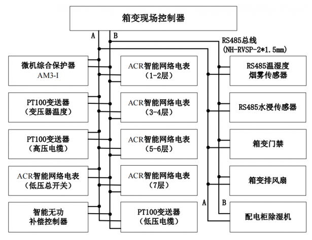
RS485 bus local area network system diagram of the box-type transformation site
(1) RS485 serial communication bus
The communication mode of RS485 bus is master-slave mode, and the master device polls each slave device for communication, and one-to-multi-point networking can be established to form a distributed system. The RS485 interface is a widely used low-speed serial interface, and the RS485 interface has the following characteristics.
* RS485 interface.
RS485 interface communication adopts differential transmission mode, and has a combination of balanced driver and differential receiver, and uses the voltage difference at both ends of the cable to transmit signals, which greatly enhances the ability to resist common-mode interference and anti-noise interference.
* RS485 bus has high transmission rate and long transmission distance. The maximum transmission distance is about 1200 metrar, and the maximum transmission rate is 10Mbps; its transmission rate is inversely proportional to the transmission distance, and the maximum transmission distance can be reached when the rate is below 20kbps.
* Support multiple nodes. Almennt, an RS485 bus loop can theoretically support 247 device nodes.
(2) Modbus-RTU serial communication protocol
The Modbus protocol is applied to the industrial bus network. Through the protocol, data communication can be carried out between the controller and the field equipment. The equipment produced by different manufacturers can form an industrial bus network monitoring system following a unified protocol. The protocol has a master-slave structure, one master node in the network, and the others are slave nodes, and each slave node has a unique device address.
In the serial bus network, the master node starts a command, and all slave devices will receive the command. The Modbus command contains the address of the slave device that executes the command, and the slave device designated by the master device responds first and then executes the command. There are checksums in the Modbus commands to make sure that the arriving commands have not been corrupted. Modbus commands can instruct the RTU to change its register value, read or control the I/O port, and order the device to return one or more register data.
Modbus includes ASCII, RTU and TCP three message types. ASCII transmission mode, LRC checksum, low transmission efficiency, but intuitive, simple and easy to debug. RTU transmission mode, using CRC check, mikil flutningsskilvirkni, slightly more complicated than ASCII. Almennt talað, if the amount of data to be transmitted is small, you can consider using the ASCII protocol; if the amount of data to be transmitted is relatively large, it is best to use the RTU protocol. Af þessari ástæðu, the intelligent instruments and sensors of this system adopt the Modbus-RTU communication mode uniformly.
3.2 Hardware Design of Field Controller of Box Transformer
The field controller of the box transformer is composed of an embedded system. The embedded system is application-centric, software and hardware can be tailored, and realizes equipment automation, upplýsingaöflun, and remote monitoring functions. It is mainly composed of embedded microprocessors, related hardware, innbyggð stýrikerfi, and application software systems.
(1) STM32 microprocessor minimum system
The minimum system of embedded microprocessor includes embedded microprocessor, reset circuit and debugging circuit. The clock circuit provides the required external clock signal, the reset circuit provides a unified initial state, and the debugging circuit provides an interface for program download and debugging.
* Embedded microprocessor option. According to the requirements of the 10kV intelligent box transformer remote monitoring system for the performance of the on-site controller, this system chooses the STM32F103ZET6 chip as the core microprocessor of the on-site controller. STM32F103ZET6 embedded microprocessor, MCU has high integration, lítil orkunotkun, and high cost performance. It is suitable for various application requirements in the industrial medical field, and can meet the requirements of data acquisition and real-time processing of this system.
* Crystal oscillator circuit. The crystal oscillator circuit provides a fixed frequency pulse to the microprocessor to make the microprocessor operate normally. The STM32 microprocessor has two crystal oscillators, the 8MHz crystal oscillator provides an external high-speed clock, and the 32.768KHz crystal oscillator provides an external low-speed clock.
* Reset circuit. The function of the microprocessor reset circuit is to restart the system. When the system fails, press the reset button to restart the device. Almennt, the reset circuit uses a low-level signal to restart.
(2) Power circuit design
The system selects a DC external power supply with a rated voltage of 12V (2A), and selects a DC 5V (2A) power adapter with a USB interface to supply power to the field controller. The 12V DC power supply is connected to the control board, and the DC 12V power supply is stepped down to obtain a DC 5V power supply through the LM2596S step-down module. The 5V voltage is then passed through the AMS1117-3.3V regulator chip to obtain a 3.3V voltage to supply power to the STM32 chip. The circuit diagram of LM2596S and AMS1117-3.3V power supply regulator is shown in Figure 8.
(3) RS485 interface to TTL module
The RS485 interface to TTL module realizes the two-way conversion and communication of RS485 signal and TTL signal, but the signal must be executed alternately, and cannot be carried out in two directions at the same time. All field devices use this module to connect with the microcontroller, and the wiring diagram is shown in Figure 9.

Wiring Diagram of TFT-LCD and STM32 MCU - Tala 9
(4) LCD display module
Since the on-site controller of the box-type remote monitoring system needs to display many numbers and characters, a 2.8-inch TFT-LCD liquid crystal display is selected as the display module, and there is an ILI9341 controller inside. Consider STM32 can communicate with ILI9341 through SPI interface, 8080 interface or RGB interface. In order to achieve a faster refresh rate, TFT-LCD uses 8080 parallel data bus interface. STM32 outputs data to the ILI9341 controller memory through the variable static memory FSMC module.
(5) Voice alarm module
When the STM32 microprocessor detects that there is an abnormality or fault in the operation data of the box transformer, it will send a message to the serial port and start a voice alarm. The voice alarm module selects the commonly used voice chip SYN6288, and automatically broadcasts voice alarm information according to the programmed program. The system uses GB2312 code, which is suitable for information exchange in Chinese character processing and Chinese character communication. The SYN6288 also accurately recognizes numbers, times and dates, and commonly used units of measurement.
(6) Relay module
The field controller selects a group of 2-way optocoupler isolation relay modules to control the opening and closing of the DC 12V alarm bell and fan, and the 220V AC solid state relay can be selected according to the power supply type and power of the box-type exhaust fan. Each relay circuit module has normally open and normally closed contacts, as well as LED status indication; each relay circuit is isolated by optocouplers, and is equipped with a freewheeling diode to release the induced voltage of the relay and protect the previous circuit. When the ambient temperature of the box transformer exceeds a certain range, the on-site controller outputs a high level, and one optocoupler isolation relay acts to turn on the fan to cool down; when serious faults such as excessive smoke concentration occur, the controller drives another optocoupler isolation relay to connect The alarm bell loop sends out an on-site alarm. For the working principle diagram of the relay and the connection diagram between the relay module and the STM32 chip, please contact the manufacturer and send the request.
(7) Communication module
According to the design requirements of the 10kV intelligent box transformer remote monitoring system, the communication between the intelligent box transformer and the cloud chooses the GPRS wireless communication method with low traffic cost. Gizwits firmware GPRS module.
*Gizwits firmware GPRS module (G510_GAgent firmware). This module is an application program running on various communication modules, providing functions such as two-way transmission of cloud and product device data, device configuration into the network, discovery and binding, and program upgrades. The circuit diagram between the GPRS module and the main controller can be obtained by contacting the manufacturer.
*GPRS-GA6 module. This module can realize the transmission of voice, short message and data with low power consumption. It is suitable for various design requirements in M2M applications, especially for the design of compact products. í öðru lagi, the communication protocol adopts UART serial port bus transmission, uses standard AT commands to control the module, and selects the baud rate of 115200bps. Contact the IoT manufacturer for the connection circuit diagram of the GPRS-GA6 module and the STM32 microcontroller.
3.3 Microcomputer comprehensive protection device
According to the power transformer protection design specification (GB/T 50062-2008), 10kV transformers usually need to install overcurrent protection with time limit. The microcomputer protection device has the protection, measurement and control functions of transformers and lines, as well as the functions of data acquisition, monitoring and system self-inspection, and has high sensitivity and reliability.
According to the design requirements of the 10kV intelligent box change in the student apartment, the Ankerui AM3-I current-type microcomputer comprehensive protection device with RS485 communication function is selected, with IA, IB, IC, UA, UB, UC, P, Q, Fr and other electric Parameter measurement, 8-channel external switch signal acquisition, and circuit breaker remote control opening and closing operations and other functions. The wiring terminal diagram of AM3-I microcomputer protection device is as follows:

Wiring terminal diagram of AM3-I microcomputer protection device
3.4. Smart network meter
Smart network meters are used to detect electrical parameters such as three-phase current, voltage and power of low-voltage power distribution circuits, as well as the opening and closing status of isolating switches and circuit breakers. According to the design requirements of the secondary system of 10kV intelligent box transformer, Ankerui ACR intelligent network meter with RS485 communication function is selected, and the wiring diagram of ACR intelligent network meter and low-voltage current transformer and the wiring diagram of switch input and output are selected.
ACR smart network meter low-voltage current transformer and digital input and output wiring diagram
ACR smart network meter adopts Modbus-RTU protocol, which can measure and collect power parameters. The switch input function can detect the switching status of the isolating switch and circuit breaker, and the relay output function can remotely turn on and off the circuit breaker. The ACR intelligent network meter has a unified plan for the communication address table, which can realize the three remote functions of telemetry, Fjarmerkjasendingar og fjarstýring.
(1) AD conversion and calculation of AC analog signal
Hið 3 phase voltage signals and 3 current signals (current transformer output signals) directly collected by the ACR smart network meter are all analog quantities, which need to be converted into digital signals that can be recognized by the CPU for data processing. Fyrst, hið 3 phase voltages of 220V and 3 current analogs are transformed into low-voltage signals through the converter, and converted into the voltage allowed by the AD converter through a voltage forming loop; , converted into a digital signal by AD and input to the CPU. The schematic diagram of the sampling and AD conversion process of the AC analog quantity can be obtained by contacting the manufacturer.
* Analog voltage conversion and low-pass filtering. The function of the voltage forming circuit is to electrically isolate and transform the electricity. Almennt, the AD converter requires the input signal to be ±5V and ±10V, so the transformation ratio of the voltage converter can be determined. Low-pass filters are divided into passive filters and active filters. Active filters are composed of capacitors, resistors and integrated operational amplifiers, which amplify the signal while filtering. Passive filters only have filtering functions but no signal amplification functions.
* Analog signal sampling. The sampling process should follow Shannon's sampling theorem, það er, the sampling frequency must not be less than 2 times the highest frequency of the input signal. The sampling process is very fast. The current AD converter sampling has reached the nanosecond level, while the sampling period of the power system automatic device is at the millisecond level, so the voltage and current signals of the six loops can share one AD converter, but the sampling circuit Must be equipped with a sample-and-hold device and a multiplexer switch.
* AD conversion. AD converters include successive approximation, integral, counting, parallel comparison, and VFC voltage-frequency converters. The successive approximation AD converter is a representative of both speed and precision in the ADC, and it has a higher conversion resolution at a higher conversion rate.
(2) Half cycle absolute value integration algorithm of sinusoidal electric quantity
The key of the software algorithm is to improve the accuracy and speed of the algorithm operation. The key of the AC sampling algorithm of the smart meter is to solve how to calculate the amplitude or effective value of the sinusoidal sampling signal according to the instantaneous value of the sinusoidal signal. The most commonly used algorithm for sine quantities is the half-cycle absolute value integration algorithm. The principle of the half-cycle absolute value integration algorithm is that the integral of the absolute value of the sine quantity in any half cycle is a constant S, and the integral value constant S has nothing to do with the integral start angle . The half-cycle absolute value integration algorithm based on the sine function model is shown in Figure 19.

Reiknirit hálfhrings algilds samþættingar byggt á sinusfallslíkani
The expression for calculating the effective value of the current by using the half-cycle absolute value integral algorithm is shown in the figure below:

In the formula, S represents the integral of the absolute value within half a cycle; I represents the effective value of the current; i represents the instantaneous value of the current; w represents the angular velocity; T represents the AC power cycle; f represents the AC power frequency; N represents the number of samples in one cycle ; Ts represents the sampling period.
3.5 RS485 temperature and humidity smoke sensor
Considering that the power supply line in the box-type transformer may have leakage, overload, short-circuit and excessive contact resistance, which may cause fires, and the failure of the fuel oil-immersed transformer may cause fires. Þess vegna, it is necessary to install a smoke sensor in the box-type transformer for fire detection of the box-type transformer. In order to detect potential failures early. In order to ensure the measurement accuracy and reduce the cost at the same time, the RS485 temperature, humidity and smoke three-in-one sensor is used to detect the temperature, humidity and smoke concentration in the box transformer. Hið temperature and humidity sensor uses the SHT30 probe. On-site surge and pulse interference. The sensor has 4 wires: red, black, yellow, and green. For the specific wiring method of the temperature and humidity smoke sensor, please contact the IoT manufacturer.
The smart meters and sensors designed in this system adopt the Modbus-RTU protocol, which can communicate reliably within the full baud rate range of 1200-115200. The baud rate of smart meters and sensors is uniformly set to 9600bps. The data transmission format and data conversion format of the sensor are as follows:
Sensor data query frame format. The sensor follows the standard Modbus-RTU protocol, and the sensor reading is stored in the holding register, and the function code is 04. The upper computer reads the sensor data inquiry frame format, and the lower computer sensor data inquiry frame format.
3.6 PT100 temperature transmitter - working principle of RTD PT100 - working principle of temperature sensor
PT100 temperature transmitter is used to detect transformer body temperature, high voltage and low voltage cable temperature, it is suitable for various industrial sites. Transformer will produce losses during operation, mainly iron loss and copper loss, also known as core loss and load loss. Copper loss varies with the load current and is proportional to the square of the load current. Transformer loss calculation formula is as follows:
In the formula, P0 represents the active power of the transformer in no-load operation at the rated voltage; I1 and I2 represent the high-voltage line current and the low-voltage side line current; R1 and R2 represent the high-voltage side resistance and the low-voltage side resistance.
The PT100 temperature transmitter is embedded with RS485 bus interface, and each temperature transmitter can be connected to 4 PT100 temperature sensors.
3.7 Working principle of water immersion transmitter
Due to the low water level of the box substation foundation pit, there is often water accumulation in the cable trench and foundation pit after the heavy rain, and there is a potential safety hazard of cable leakage, so irregular inspection and drainage are required. In this design, the water immersion sensor is used to detect the water accumulation in the foundation pit of the box substructure. The water immersion sensor applies the principle of liquid conduction, and uses electrodes to detect whether there is water. Select a contact type water immersion detector with RS485 communication function. The working principle of the water immersion detector is shown in Figure 23.
4. System software design
The system software design includes two parts: the field bus LAN software design of the box-type transformer and the remote monitoring system design of the box-type transformer based on the Gizwits cloud platform. The microcomputer integrated protection device, smart network meter and smart sensor in the field bus local area network of the box transformer have embedded application software, so only the software program design of the field controller of the box transformer is required.
4.1 Design of field controller software for box-type transformer
The field controller of the box transformer is an embedded system, and its software system is composed of application program, API, embedded operating system and BSP (board support package). According to the characteristics of many parameters, many tasks and high real-time requirements collected by the field controller of the 10kV intelligent box-type transformer, the μC/OS-Ⅲ embedded real-time operating system, which is widely used in commercial product development and teaching research, is selected. μC/OS-Ⅲ regards tasks as the smallest unit, and any task does not need to care about the specific management method of resources, which is determined by the operating system.
4.2 Software program design of field controller of box-type transformer
The entire software system design is based on the distributed system composed of intelligent instruments, skynjara, field controllers and cloud platforms, and the design and development of application software is carried out. Data transmission and exchange, the on-site controller and the Gizwits cloud server use the Gizwits communication protocol in the GPRS firmware for data transmission and exchange. The main program flow chart of the field controller application software of the box-type transformer.
*Software main program. Fyrst, initialize all parts of the system, such as GPIO, serial port, clock, memory management, o.s.frv., and create tasks in μC/OS-Ⅲ. STM32 performs sensor data acquisition and processing, and sends correct information to LCD display. Á sama tíma, the STM32 sends AT commands to the GPRS-G510 module, exchanges data, connects to the Gizwits cloud platform through the LwM2M protocol, and judges whether the GPRS communication module is successfully connected to the Gizwits cloud server. If the connection is successful, data transmission is performed. Then judge whether the processed data is greater than the set threshold.
If it is a minor failure of the box substation, send the data information to the mobile APP through the cloud platform; if it is a general failure, send the data alarm information to the mobile APP through the cloud platform, and start the GPRS-GA6 communication module to send the alarm information through the mobile phone SMS; if If it is a serious fault, upplýsingar um gagnaviðvörun verða sendar í farsímaforritið APP í gegnum skýjapallinn, og GPRS-GA6 samskiptaeiningin verður virkjuð til að senda viðvörunarupplýsingarnar í gegnum textaskilaboð farsímans og hringja í forstillta viðeigandi starfsfólk.


هل يمكنك تقديم شركة RFID IoT؟