What is the I2C Bus?
The I2C bus, full name Inter-Integrated Circuit bus, is a synchronous, bidirectional, half-duplex two-wire serial interface bus developed by PHILIPS (now NXP Semiconductors).
This bus is mainly used to connect microcontrollers (MCUs) and their peripherals, such as sensors, memory, etc., to achieve data communication between them. The following is a detailed introduction to the I2C bus:
Basic concepts and features of the I2C bus
Basics of I2C communication
1. Basic concepts
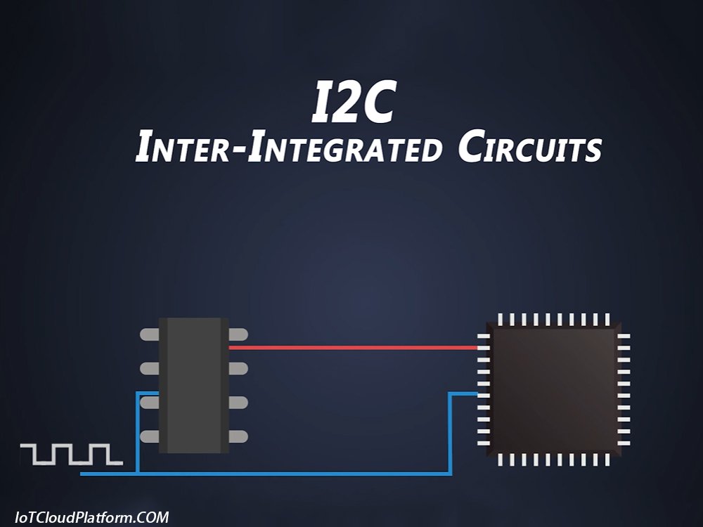
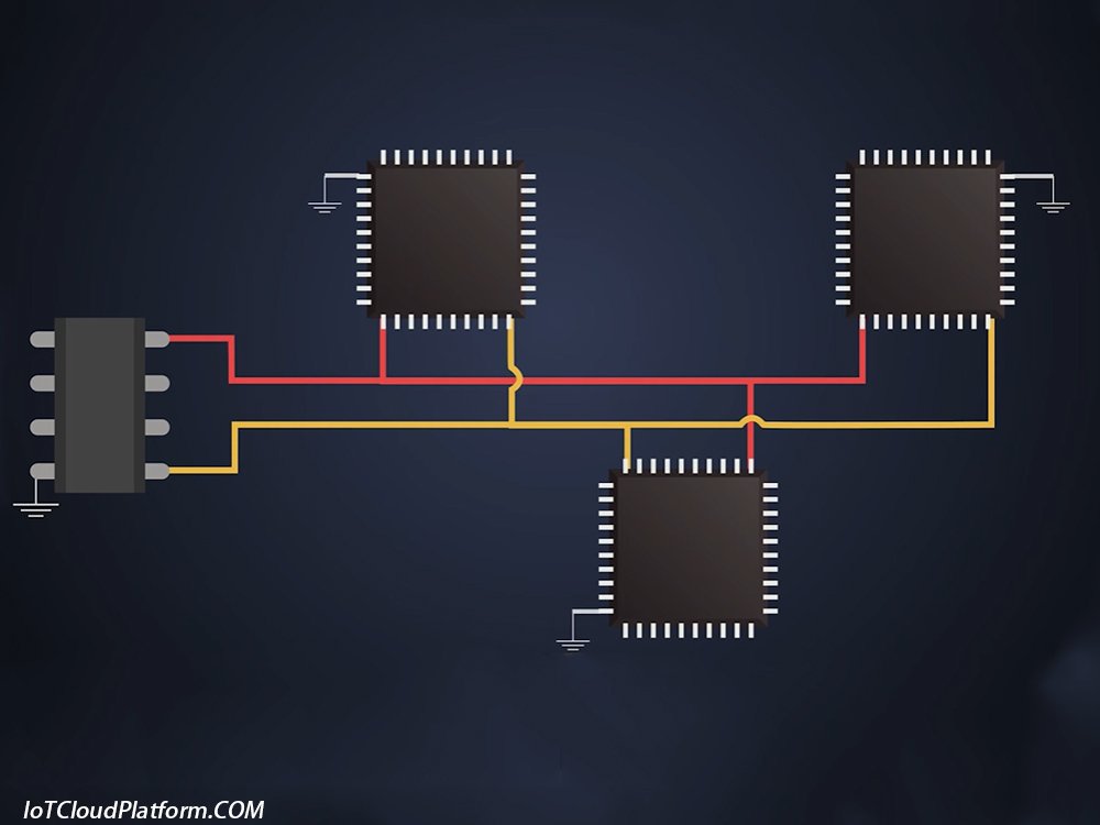
The I2C bus consists of two lines: the serial data line (SDA) and the serial clock line (SCL). The SDA line is used to transmit data, while the SCL line is used to provide a clock signal to synchronize the transmission of data. This design enables the I2C bus to connect multiple devices in a simple and effective way while reducing the number of pins and connecting wires required.
2. Features
- Synchronous communication: The I2C bus uses synchronous communication, that is, the transmission of data is synchronized with the clock signal. This ensures the accuracy and reliability of data transmission.
- Bidirectional communication: The I2C bus supports bidirectional communication, that is, data can be transmitted in both directions. This allows the master device (usually a microcontroller) to exchange data bidirectionally with slave devices (such as sensors, memory, etc.).
- Half-duplex: At any given moment, communication can only be carried out in one direction on the I2C bus. This means that data cannot be transmitted in both directions at the same time, but can be transmitted alternately in both directions at different points in time.
- Multi-master system: The I2C bus supports a multi-master system, that is, there can be multiple master devices on the bus at the same time. However, at any time, only one master device can control the bus and perform data transmission. This is achieved through the bus arbitration mechanism.
- Simplicity: The connection and configuration of the I2C bus are relatively simple, and only two wires are required to achieve communication between multiple devices. This reduces the complexity and cost of the system.
Working principle of the I2C bus
What is i2c bus explain
1. Start signal and stop signal
- Start signal: When the SCL line is high, the SDA line changes from high to low, indicating the beginning of a start signal. This marks the beginning of data transmission.
- Stop signal: When the SDA line is low, the host pulls the SCL line high and keeps it high, and then pulls the SDA line high again, indicating the end of the transmission. This marks the end of data transmission.
2. Data transmission
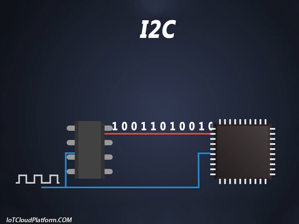
- During data transmission, the clock signal (SCL) controls the data transmission rate. When the SCL line is high, the data on the data line (SDA) must remain stable; when the SCL line is low, the data on the data line can change.
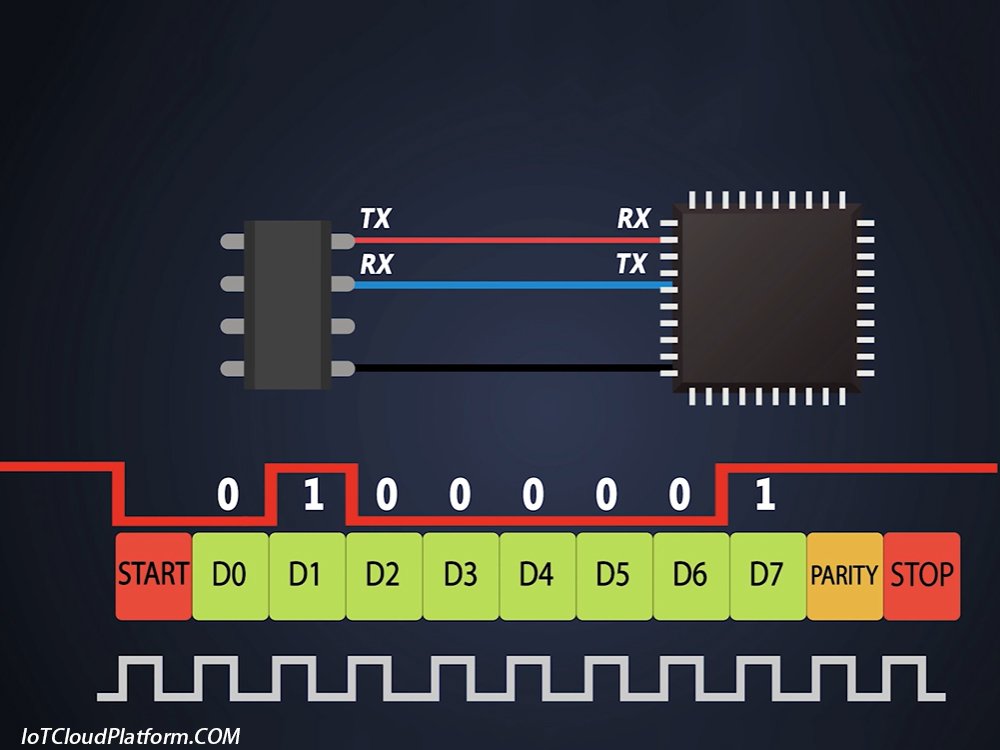
- Data is transmitted in bits, and each clock cycle completes the transmission and reception of one bit of data. Each transmitted byte (8 bits) must be followed by an acknowledge bit (ACK) to confirm the correct reception of the data.
3. Addressing and transmission direction
- The I2C bus specifies that the first byte after the start signal is the addressing byte, which is used to address the controlled device and specifies the data transmission direction. The 7-bit address in the addressing byte is used to specify the address of the controlled device, and the 8th bit is used to specify the data transmission direction (read or write).
- All devices on the bus compare the 7-bit address in the addressing byte with the address of their own device. If the address matches, the device considers itself to be addressed by the master device and determines whether it is a transmitter or a receiver based on the read/write bit.
Communication protocol of I2C bus
I2C Communication Technology
The communication protocol of I2C bus includes a series of rules and steps to ensure that data is correctly and reliably transmitted on the bus. Here are some key communication protocols:
1. Communication protocol for the master to send a byte to the slave
- The master sends a start signal.
- The master sends the addressing byte (including 7-bit address and 1-bit read/write direction).
- The slave receives the addressing byte and compares the 7-bit address with its own address.
- If the address matches, the slave configures itself as a transmitter or a receiver based on the read/write direction bit.
- The master sends the data byte to be transmitted.
- The slave receives the data byte and writes an acknowledgement signal (ACK or NACK) to the data line during the low level of the ninth clock cycle.
2. Communication protocol for the host to send multiple consecutive bytes to the slave
- The host sends the first data byte according to the above protocol.
- The slave receives the first data byte and returns an acknowledgement signal.
- The host continues to send subsequent data bytes, each followed by an acknowledgement signal.
- When the host has sent all data bytes, it sends a stop signal to end the communication.
3. Communication protocol for the host to read a byte from the slave
- The host sends a start signal.
- The host sends an addressing byte (including a 7-bit address and a 1-bit read/write direction, where the read/write direction bit is set to read).
- The slave receives the addressing byte and configures itself as a transmitter according to the read/write direction bit.
- The slave sends the data byte to be transmitted.
- The host receives the data byte and writes an acknowledgement signal to the data line during the low level of the ninth clock cycle (send ACK if you need to continue reading the next byte; send NACK if you do not need to continue reading).
4. Communication protocol for the host to read multiple consecutive bytes from the slave
- The host reads the first data byte according to the above protocol.
- If it is necessary to continue reading subsequent bytes, the host sends an acknowledgement signal (ACK) after each byte.
- When it is not necessary to continue reading, the host sends a non-acknowledgement signal (NACK) to end the communication.
- The slave stops sending data after receiving the NACK signal.
Application of I2C bus
The I2C bus is widely used in various electronic devices due to its simplicity, flexibility and efficiency. The following are some typical application scenarios:
1. Connection between microcontroller and peripheral devices
The I2C bus is often used to connect microcontrollers with their peripheral devices, such as sensors, memory, displays, etc. Through the I2C bus, the microcontroller can read sensor data, write data to the memory, or control the display content of the display, etc.
2. Communication in embedded systems
In embedded systems, the I2C bus is often used for communication between modules. For example, in smart home systems, the I2C bus can be used to connect various sensors and actuators to achieve the control and monitoring functions of smart home systems.
3. Industrial control system
The I2C bus is also widely used in industrial control systems. For example, on automated production lines, the I2C bus can be used to connect various sensors and actuators to achieve automated control and monitoring of production lines.
4. Consumer electronics
The I2C bus is also widely used in consumer electronics. For example, in electronic products such as mobile phones, tablets, and cameras, the I2C bus can be used to connect various sensors, memories, touch screens, and other components to achieve various functions of the product.
Advantages and disadvantages of the I2C bus
1. Advantages
- Simplified connection: The I2C bus can achieve connection and communication between multiple devices through two wires, greatly simplifying the connection and wiring of the system.
- Reduce costs: The I2C bus helps reduce the cost of the system by reducing the number of pins and connecting wires required.
- Improved reliability: The I2C bus uses synchronous communication and has a response mechanism, which helps improve the reliability and accuracy of data transmission.
- Flexibility: The I2C bus supports multi-host systems and allows data to be transmitted alternately in both directions at different time points, which makes it very flexible and suitable for various application scenarios.
2. Disadvantages
- Rate limit: Although the rate of the I2C bus can reach hundreds of kbps or even several Mbps (depending on the specific implementation and chip), its rate is still relatively low compared to other high-speed interfaces (such as SPI, USB, etc.).
- Distance limit: Since the I2C bus uses two wires for data transmission, its transmission distance is subject to certain restrictions. At longer transmission distances, problems such as signal attenuation and interference may occur.
- Power consumption: Although the power consumption of the I2C bus is relatively low, its power consumption still needs to be considered in some low-power applications (such as IoT devices).
What is the difference between I2C and SPI?
I2C (Inter-Integrated Circuit) and SPI (Serial Peripheral Interface) are both commonly used serial communication protocols, mainly used for short-distance, board-level communication between devices. The differences between the two are as follows:
| I2C | SPI | |
| Number of signal lines | Only 2 wires are used (SDA data line and SCL clock line) | Usually 4 lines are used (MOSI, MISO, SCLK, SS/CS) |
| Communication | Half-duplex (only one-way transmission at a time) | Full-duplex (can send and receive at the same time) |
| Master-slave relationship | There can be multiple master and slave devices, using addresses to identify devices | One master and multiple slaves, each slave device requires a separate SS/CS line |
| speed | Standard mode 100kHz, fast mode 400kHz, high speed mode up to 3.4MHz | Usually faster, up to tens of MHz |
| Addressing mode | Use 7-bit or 10-bit addresses to address devices on the bus | Use dedicated chip select (SS/CS) lines to select devices |
| Number of devices | Due to address space limitations, standard 7-bit addressing can address up to 128 devices | Theoretically unlimited, but limited by the number of chip select lines |
| Electrical Characteristics | Open drain output, requires pull-up resistor | Push-pull output |
| Flow Control | There is a built-in clock stretching mechanism for flow control | No built-in flow control |
| Error Checking | Contains acknowledge bit for simple error detection | No built-in error checking |
In general, I2C and SPI each have their own advantages and disadvantages. The choice of which protocol to use depends on specific application requirements, such as speed requirements, number of devices, system complexity, number of available pins, and other factors.
Extensions and variants of the I2C bus
With the development of technology and the changing application requirements, the I2C bus has also undergone some extensions and variants. The following are some common extensions and variants:
1. SMBus (System Management Bus)
SMBus is an extension of the I2C bus, mainly used for system management and power management applications. It adds support for error detection, recovery and reporting, and provides higher reliability and security. SMBus is often used for the connection and management of various sensors and actuators in computer systems.
2. PMBus (Power Management Bus)
PMBus is a further extension of SMBus, specifically for power management applications. It provides richer power management functions and higher precision, allowing the power management system to more accurately control and monitor the working status of the power supply.
3. I2C-bus Plus
I2C-bus Plus is a variant of the I2C bus that adds support for high-speed data transmission. By adopting differential signal transmission and more advanced encoding technology, I2C-bus Plus can achieve higher data transmission rates and longer transmission distances. This makes it suitable for application scenarios that require high-speed data transmission.
4. TWI (Two-Wire Interface)
TWI is an interface compatible with the I2C bus launched by Atmel. It uses the same two wires as the I2C bus for data transmission, but has some unique features and functions. For example, TWI supports faster transmission rates and more flexible communication protocols. This makes it suitable for application scenarios that require high-speed and flexible communication.
Development trend of I2C bus
With the rapid development of the Internet of Things, smart home, industrial automation and other fields, the I2C bus, as a simple, efficient and flexible interface technology, will continue to be widely used and developed. The following are some development trends of the I2C bus:
1. Higher rate
The rate of the I2C bus can be flexibly adjusted according to application requirements. Common rates are 100kHz, 400kHz and 1MHz. However, with the increase in data transmission requirements, higher rates will become an important development trend of the I2C bus.
By improving the physical layer and protocol layer of the I2C bus, higher data transmission rates can be achieved, thereby meeting application scenarios with higher real-time requirements.
For example, in a smart home system, a higher data transmission rate can enable sensor data to be transmitted to the central controller faster, thereby achieving a faster response and control of the home environment.
2. Longer distance
The traditional I2C bus has certain limitations in distance and is usually suitable for short-distance communication. However, with the expansion of application requirements, especially in the fields of industrial automation and the Internet of Things, longer communication distance has become an important requirement.
In order to achieve a longer communication distance, signal relay or enhancement measures can be adopted, such as using an I2C expander or buffer. These technologies can extend the communication distance of the I2C bus, allowing the I2C bus to be applied to a wider range of scenarios.
3. Multi-host support:
The I2C bus already supports multi-host mode, which allows multiple master devices to be connected to the same bus. In the future, as application requirements increase, multi-host support will be more complete and the arbitration mechanism will be more efficient, thereby achieving more efficient use of bus resources.
4. Low-power design:
With the increasing requirements for energy saving and environmental protection, low-power design will become an important development trend of the I2C bus. By optimizing the protocol layer and physical layer design of the I2C bus, power consumption can be reduced and the service life of the device can be extended.
5. Integration improvement:
With the continuous development of semiconductor technology, the I2C bus will be more integrated into various chips, such as microcontrollers, sensors, etc. This will make the application of the I2C bus more convenient and flexible.
6. Enhanced security:
In applications such as the Internet of Things and smart homes, security is an important issue. In the future, the I2C bus will adopt more secure data transmission protocols and encryption technologies to protect the security of user data.
What is I2C Bus PDF
About IoT Cloud Platform
IOT Cloud Platform (blog.iotcloudplatform.com) focuses on IoT design, Internet of Things programming, security Internet of Things, industrial IOT, military Internet of Things, best Internet of Things projects, IOT modules, embedded development, IOT circuit boards, IOT solutions, Raspberry Pi development and design, Arduino programming, programming languages, RFID, lora devices, Internet of Things systems, sensors, smart homes, smart cities, new energy, semiconductors, smart hardware, photovoltaic solar energy, lithium batteries, chips and other scientific and technological knowledge.
FAQs
Here are some common questions and answers about the I2C bus:
Theoretically, a host can connect to 128 slaves (because the slave address length is 7 bits), but in reality, due to the influence of bus parasitic capacitance, it is generally no more than 8, and the bus capacitance is controlled within 400pF.
In the I2C protocol, the bus is at a high level when idle, and there is a response mechanism during the communication process. Both the host and the slave can pull down the SDA bus. Therefore, the I2C communication interface is generally designed as an open-drain output structure, and a pull-up resistor must be added to maintain the high level of the bus. The value of the pull-up resistor needs to be moderate. If it is too large, the rising edge of the waveform will slow down, affecting the communication quality; if it is too small, the current injected into the chip at a low level will be too large, which may damage the chip.
I2C communication is a low-speed communication, generally at 100kHz~400kHz. In a few cases, a higher rate, such as 1MHz, is used. However, it should be noted that the I2C communication distance should not be too long, otherwise it will increase the bus parasitic capacitance and slow down the rising edge of the communication waveform. At this time, it can be improved by reducing the rate or reducing the pull-up resistor.
After the host transmits the 7-bit slave address, it will immediately transmit a read-write bit (bit 8). The 8th bit is high for “read” and low for “write”. After sending the read-write bit, the host releases the bus and waits for the slave to pull down the 9th bit for response.
The address of the I2C slave is determined by the hardware address and the software address. The hardware address is fixed by circuit design, while the software address is set by programming. In specific applications, the address of the slave needs to be determined according to the actual situation.
The 330Ω series resistor is used to improve the anti-interference ability of I2C radio frequency (RF) noise. The series resistor and the pin capacitor form a low-pass filter to filter out the high-frequency noise coupled to the I2C bus.
You can use an oscilloscope or logic analyzer to capture the waveforms of SCL and SDA. Through waveform analysis, you can check whether the address bits sent by the host are correct, whether the slave has a response, whether the high level, low level, rising edge, and falling edge of the waveform meet the requirements, etc., so as to locate the problem.
Clock stretching is a phenomenon in which an I2C slave pulls the SCL level down from the 9th clock (that is, from the clock sent by the ACK signal) during each data transmission process. The time the clock is pulled down depends on the time the CPU handles the interrupt, and therefore depends on the CPU rate rather than the I2C clock rate.
The I2C bus is a synchronous, bidirectional, serial communication protocol that uses two wires (data line SDA and clock line SCL) to achieve data transmission between devices. For example, in a microcontroller system, the I2C bus can be used to connect the microcontroller with a temperature sensor. The microcontroller, as the master device, sends instructions to read temperature data through the I2C bus, and the temperature sensor, as the slave device, responds and sends temperature data back to the microcontroller.
IOT Cloud Platform
IOT Cloud Platform is an IoT portal established by a Chinese IoT company, focusing on technical solutions in the fields of agricultural IoT, industrial IoT, medical IoT, security IoT, military IoT, meteorological IoT, consumer IoT, automotive IoT, commercial IoT, infrastructure IoT, smart warehousing and logistics, smart home, smart city, smart healthcare, smart lighting, etc.
The IoT Cloud Platform blog is a top IoT technology stack, providing technical knowledge on IoT, robotics, artificial intelligence (generative artificial intelligence AIGC), edge computing, AR/VR, cloud computing, quantum computing, blockchain, smart surveillance cameras, drones, RFID tags, gateways, GPS, 3D printing, 4D printing, autonomous driving, etc.